Intro:
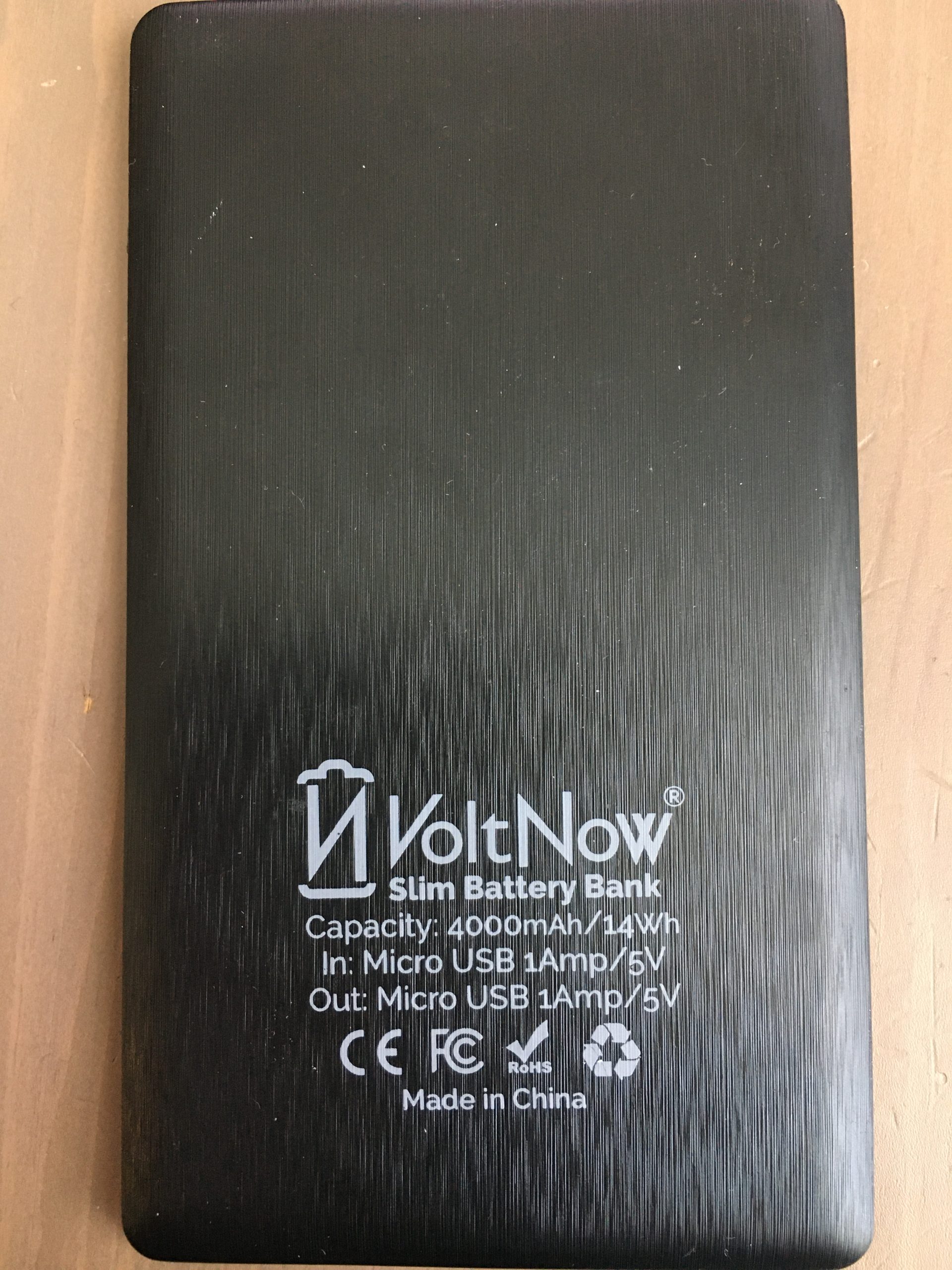
It seems that it’s easier and cheaper to find a complete 5V USB power bank than the individual battery. For example, I snagged this VoltNow for $3! (few years back)
Like many others I was hoping to use it to power an ESP32 or other small embedded device. Problem is that the power bank has internal smarts that turn off the output if there is no load, or very little load. So having a micro that will go to sleep for extended amounts of time, would trigger the power-off on the battery bank.
There are suggestions out there to add a constant power draw resistor or some smart circuitry that would draw just enough, and for long enough to trick the battery bank into thinking that it should stay on.
I’ve opened up this particular battery pack to see if I can make sense of the circuitry and perhaps find a better option.
Internals:
Disassembly is fairly easy – carefully pry around the perimeter. Inside we find a 4000mAh 3.7V battery, that by itself is worth more than $3 if bought on Amazon. There is also a PCB with a few components. Let’s examine what is what and try to keep the magic smoke inside the ICs.
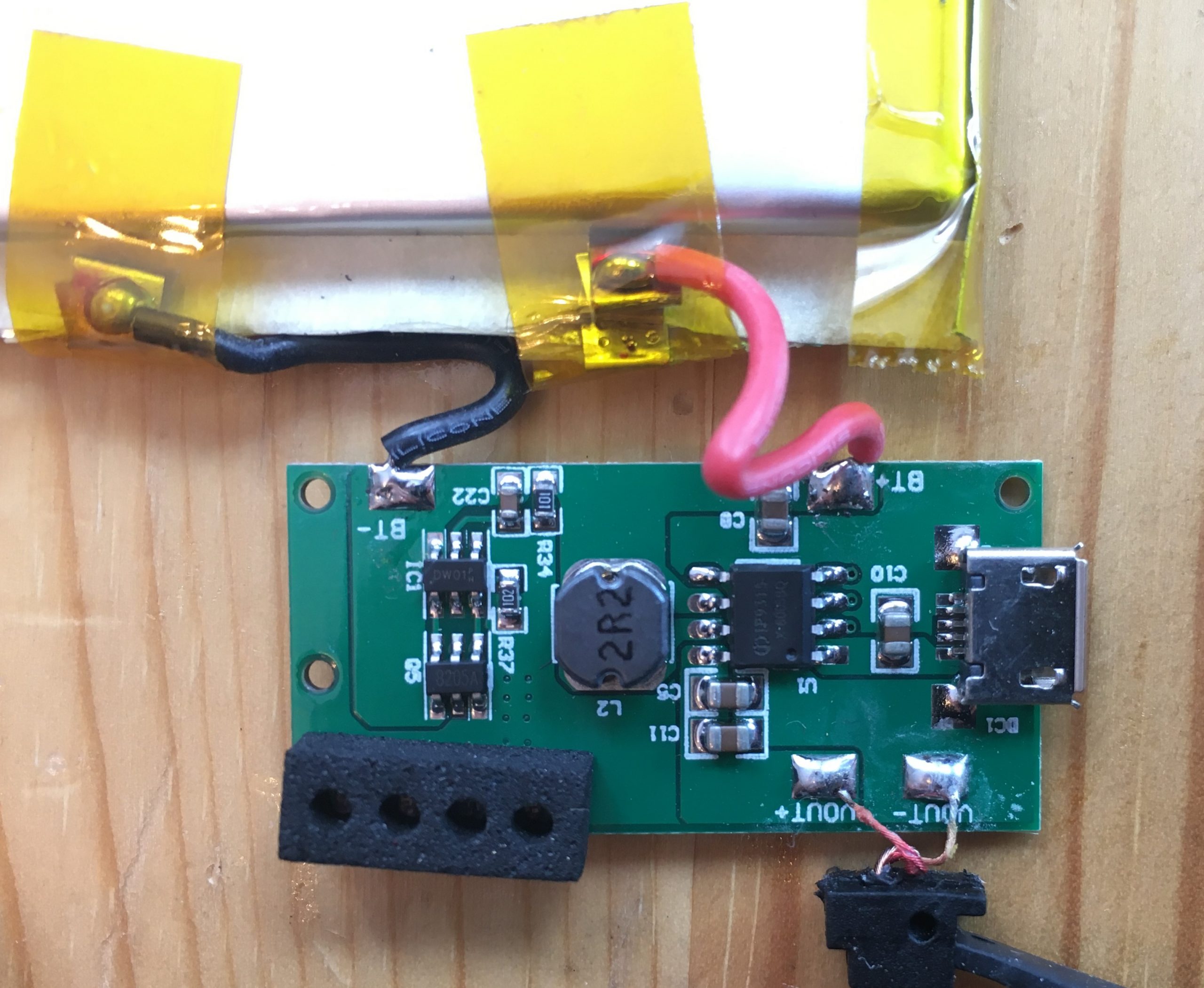
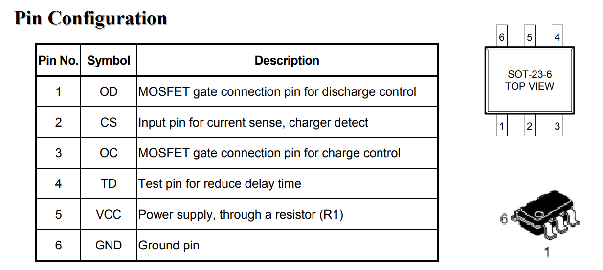
IC1 – DW01 – One Cell Lithium-ion/Polymer Battery Protection IC.
The DW01-P battery protection IC is designed to
protect lithium-ion/polymer battery from damage or
degrading the lifetime due to overcharge,
overdischarge, and/or overcurrent for one-cell
lithium-ion/polymer battery powered systems, such as
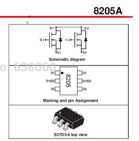
cellular phones. DW01-P controls a dual MOSFET (switch) – 8205A
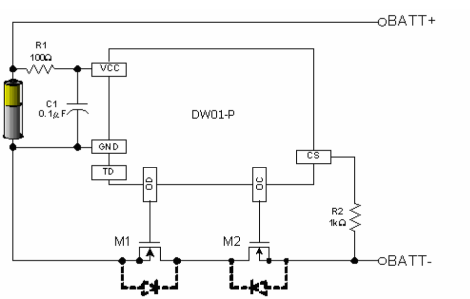
Q5 – 8205A – Dual N-Channel Enhancement Mode MOSFET
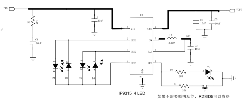
U1 – IP9315 – Highly integrated mobile power SOC. Datasheet is in Chinese but Google does a fairly good job translating to English.

Re-Wiring
This particular batter pack seems easy enough to re-wire for my needs.
Option 1: Wire directly to the battery leads BT+/BT- which will give me direct, unmanaged access to the battery. This may be ok if the microcontroller board has its own battery management controller.
Option 2: Wire to BT+ and S1 of 8205. This will still keep the DW01-P and 8205A in the loop and provide the over-discharge protection.
Keep in mind, that in both cases the IP9315IC is not used so the output will be un-regulated 3.7-4.2v from the battery.